Design and implementation of a controlled low-cost ventilator for emergency use on ICU patients
Diseño e implementación de un ventilador de bajo costo controlado para uso de emergencia en pacientes en UCI (Unidades de Cuidados intensivos)
Anibal Ruiz-Barquero1, Adrian Quesada-Martinez2, Randall Chacon-Cerdas3, Anny Alfaro-Lopez4, Wilson Bermudez-Campos5, Hamlet Loria-Mesen6, Fabio Rojas-Fernandez7
Fecha de recepción: 11 de agosto, 2023
Fecha de aprobación: 30 de noviembre, 2023
Ruiz-Barquero, A; Quesada-Martinez, A; Chacon-Cerdas, R; Alfaro-Lopez, A; Bermudez-Campos, W; Loria-Mesen, H; Rojas-Fernandez, F. Design and implementation of a controlled low-cost ventilator for emergency use on ICU patients. Tecnología en Marcha. Vol. 37, No 3. Julio-Setiembre, 2024. Pág. 156-169. https://doi.org/10.18845/tm.v37i2.6838
Keywords
Breathing frequency; pandemic; SARS-Cov-2; tidal volume; ventilator.
Abstract
The worldwide outbreak of the SARS-CoV-2 virus led to a shortage of hospital ventilators worldwide. During recovery, these devices were crucial for patients in Intensive Care Units (ICUs). However, countries like Costa Rica faced difficulties acquiring these devices due to high demand in the world. To address this issue, professionals and students from the Costa Rica Institute of Technology have developed a prototype of a mechanical ventilator. This ventilator incorporates PIDs and Fuzzy Logic algorithms and features a user-friendly graphic interface based on PyQt5/GraphicsView, designed with input from medical experts. The ventilator is easy to assemble and highly portable. Initially, the ventilator successfully underwent testing using advanced patient simulators, namely Gaumard HAL S3201 and Gaumard NOELLE S574.100. Subsequently, it underwent a successful real-world test using animals. The tests involved varying the breathing rate from 10 to 30 breaths per minute, adjusting the tidal volume from 250 to 800 mL with automatic control of a 50 mL increase, and manipulating the I: E ratio from 1:1 to 1:5.
Palabras clave
Frecuencia respiratoria; Pandemia; SARS-Cov-2; Volumen tidal; ventilador.
Resumen
El brote mundial del virus SARS-CoV-2 provocó una escasez de ventiladores hospitalarios en todo el mundo. Durante la recuperación, estos dispositivos fueron cruciales para los pacientes en las Unidades de Cuidados Intensivos (UCI). Sin embargo, países como Costa Rica enfrentaron dificultades para adquirir estos dispositivos debido a la alta demanda en el mundo. Para abordar este tema, profesionales y estudiantes del Instituto Tecnológico de Costa Rica han desarrollado un prototipo de ventilador mecánico. Este ventilador incorpora algoritmos PID y Fuzzy Logic y presenta una interfaz gráfica fácil de usar basada en PyQt5/GraphicsView, diseñada con aportes de expertos médicos. El ventilador es fácil de ensamblar y es portátil. Inicialmente, el ventilador se probó con éxito utilizando simuladores de pacientes avanzados, concretamente Gaumard HAL S3201 y Gaumard NOELLE S574.100. Posteriormente, se sometió con éxito a una prueba en el mundo real utilizando animales. Las pruebas implicaron variar la frecuencia respiratoria de 10 a 30 respiraciones por minuto, ajustar el volumen tidal de 250 a 800 ml con control automático con aumentos de 50 ml y manipular la relación I:E de 1:1 a 1:5.
Introduction
The coronavirus disease (COVID-19) generally causes mild symptoms only; however, people with underlying medical problems such as cardiovascular disease, diabetes, chronic respiratory disease, or cancer are most likely to develop serious illnesses [1]; those cases require hospitalization. According to The National Institutes of Health (NIH) in some hospitals in the United States, more than 25% of hospitalized patients require ICU care, mostly due to acute respiratory failure. In adults with COVID-19 and acute hypoxemic respiratory failure, conventional oxygen therapy may be insufficient to meet the oxygen needs of the patient [2].
Mechanical ventilation is a form of life support. A mechanical ventilator is a machine that takes over the work of breathing when a person is not able to breathe enough on their own. When a person is not able to breathe on their own or has difficulties doing it, a mechanical ventilator is required. Mechanical ventilation has been used in ICUs care and the need for mechanical ventilation in those who are critically ill is high ranging from 30 to 100 percent [3] [4]. With the rapid increase in COVID-19 cases, hospitals around the world have experienced shortages of resources, including mechanical ventilators. In the particular case of Costa Rica, while sanitary measures were taken to cut down the infection rate when the pandemic status was declared in 2020, the number of cases nationwide reached at some point at a rapid pace, and with them, the ICU occupation. As a response to a possible saturation of the health system, universities and companies worldwide have designed and manufactured low-cost ventilators, easy to assemble and with accessible materials.
This work presents the validation process and control detailing for variables for the low-cost mechanical ventilator designed at the Costa Rica Institute of Technology. Designing and assembly of the respirator have been performed by the Materials and Electronics engineering departments together. Classic PDIs control the volume of air provided to patients and a Fuzzy Logic algorithm controls the mixing of medical components, e.g. oxygen and air.
Work basics
The construction and development of the ventilator have been engineered to ensure its efficacy in critical medical emergencies, aiming to save as many lives as possible.
Main Structure
The basic structure of mechanical ventilator is where the electronic circuits and mechanical pneumatic circuits are contained. The electronic circuits and mechanical pneumatic circuits distribution inside the box were made based on the British model from Gtech [5]
Operation verification
The crucial parameters of mechanical ventilation, such as respiratory rate (breaths per minute), inspiratory airflow, and pressure, which are regulated by the ventilator, adhere to the requirements set by the Ministry of Health (MINSA). To ensure safety and efficacy, the ventilators used in clinics and hospitals undergo regular validation and calibration using lung simulators. These validations are conducted to meet the safety and efficacy standards set by the U.S. Food and Drug Administration (FDA). The work described in [6] explains the optimal operation of a cost-effective mechanical ventilator.
Automatic Digital Controller
An automatic digital controller that could control the use of the BVM described by [7], empowered with the implementation of stability and precise control, a digital controller, and a feedback system according to the work done by [8] to have a portable high-frequency ventilator. A screen is needed to show the patient’s oxygen saturation and heart rates in the same way as the work done by [9], considering the layout of the data on the screen and the provision of natural and fundamental requirements for a respirator ware made in the same way as [10].
Methodology
This section describes the procedure to create all stages and parts of the controlled low-cost ventilator for the device shown in Fig. 1. The modular setup on Fig. is assembled to run the test for the purpose of this work.
Design Strategy and Materials for the construction of an emergency mechanical ventilator
As mentioned earlier, the design approach prioritized the creation of an affordable and easily constructed mechanical ventilator. The design was derived from an existing model [5] but underwent several modifications to create a functional prototype, and readily available parts were utilized. It was essential for these parts to withstand prolonged and continuous usage since patients typically spend extended periods in the ICU, necessitating uninterrupted operation of the ventilators. Additionally, any failure of the primary ventilator components would be deemed critical.
The components and materials employed in the mechanical ventilator can be categorized into two sections: pneumatic (Table I) and electrical (Table II). Let’s begin with the pneumatic section: the prototype utilizes a manual resuscitator, commonly referred to as an Ambu bag, as the ventilation mechanism. A plastic syringe equipped with a header is connected to two metallic springs, which, in turn, actuate the movement of the Ambu bag, replicating the breathing process. Additionally, various tubes facilitate the transportation of oxygen throughout the system and allow for the patient’s intubation.
Table 1. Pneumatic parts of the respirator.
|
Equipment |
Description |
Quantity |
|
Ambu Bag |
Ambu 1.5L |
1 |
|
Springs |
Metalic |
2 |
|
Syringe |
60 CC |
1 |
|
Header |
3D printed |
1 |
|
Lower syringe holder |
3D printed |
1 |
|
Upper syringe holder |
3D printed |
1 |
|
One-way flow control valve |
FESTO GR-M5-B (151213) |
1 |
|
Push-in elbow connector for solenoid valve |
FESTO QSL-G 1/8 (186117) |
6 |
|
Push-In fitting for solenoid valve |
FESTO QS-G1/8-6-I (186107) |
3 |
|
Push-In fitting for solenoid and flow valves |
FESTO QSM-M5-6-I-R (133005) |
4 |
|
Push-in elbow connector for solenoid valve |
FESTO QSML-M5-6 (153335) |
3 |
|
Push-in fitting for proportional valve |
FESTO QSM-1/8-6 (153307) |
4 |
|
Push-In fitting for flow sensor |
FESTO QS-G1/8-6 (186096) |
2 |
|
Push-In Elbow Connector |
FESTO QSL-6 (153071) |
As required |
|
Push-in T-connector |
FESTO QST-6 (153129) |
As required |
|
Cross Push-In Connector |
FESTO QSMX-6 (153380) |
As required |
|
Tubes |
FESTO PUN-6X1-BL (159664) |
As required |
Regarding the electrical part, the equipment description and quantity are detailed in table 2.
Table 2. Electrical Parts of the respirator.
|
Equipment |
Description |
Quantity |
|
Touch Screen |
FESTO CDPX-X-A-W-7 (574411) |
1 |
|
Power Source |
FESTO CACN-3A-1-5 (2247681) |
1 |
|
Solenoid valve |
FESTO MFH-3-1/8-S (7958) |
3 |
|
Valve coil |
FESTO MSFG-24/42-50/60 (4527) |
3 |
|
Proportional pressure control valve |
FESTO VPPE-3-1-1/8-6-010-E1 (557772) |
2 |
|
Flow sensor |
FESTO SFAH-50U-G18FS-PNLK-PNVBA-M8 (8058473) |
1 |
|
Cables |
22 AWG |
As required |
Finally, all parts are assembled in a 3 mm thick stainless-steel case as shown in Fig. 1.
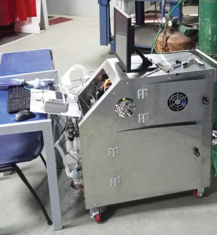
Figura 1. Lateral view of the respirator with metal case.
Volume control for achieving Tidal parameter
The volume control part for this respirator; is made up of flow and pressure sensors, a proportional differential valve, a solenoid valve, and a PWM PCA9685 module. The proportional valves used are the VPPE-3-1-1/8-6-010-E1 from FESTO, which are pressure-controlled valves. This is shown in Figure 2 and is used to regulate the pressure in the pneumatic circuit. The solenoid valve MFH-3-1/8 Festo is a mechanical device for regulating and controlling air. These devices control the flow of compressed air that feeds the syringes. Quick Exhaust valve G1/4, 1100L/min, .5-10 bar allows air to be immediately ejected through the exhaust port.
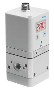
Figura 2. proportional valves used are the VPPE-3-1-1/8-6-010-E1, FESTO.
Pneumatic arrangement for valves management
The physical interface for controlling the blending of medical air and oxygen consists of two pressure regulators, each linked to a proportional flow control valve. This configuration effectively regulates the fraction of inspired oxygen (FiO2) value by controlling the mixture composition.
The outputs of the flow control valves are connected to the SFAH (static flow accuracy and humidity) sensor, which measures and displays the flow rate supplied to the patient in liters per minute (l/min). The volume control has a proportional pressure regulator linked to a solenoid valve. The solenoid valve, in turn, is connected to the exhaust valve, allowing the release of the gas from the pneumatic cylinders or syringes.
The monitoring system comprises a pressure sensor that continuously monitors the airway pressure and a flow sensor that measures airflow during the inspiration cycle. The flow data is then inputted into the control unit and undergoes processing to calculate the volume for the volume control algorithm. Additionally, an oxygen sensor measures the oxygen level in the mixture and provides feedback to the control unit from which the mixture control algorithm regulates the oxygen concentration.
PID control to keep Tidal Volume at the setpoint
Utilized within closed-loop systems, a PID controller serves to stabilize and reach the desired output state. Comprising three distinct elements - Proportional, Integral, and Derivative - this controller derives its name from their collective contribution. This control method is widely applicable across a range of diverse control systems [11]. In this specific project segment, a PI controller is employed due to its simplicity, enabling the achievement of functional outcomes using this type of control strategy.
The mathematical model for tidal volume is not established within the designed system and proves challenging to ascertain through analytical design approaches. Thus, it is determined by collecting data from the proximal flow sensor (SFM3300-AW) when the input is activated. Subsequently, this data is used to formulate the model using the Ident function in Matlab, then computed by an empirical experiment instead of mechanical models such as Lagrangian or Newtonian.
The model estimation is directed towards the inspiratory phase, as during the expiratory phase, the ventilator mainly awaits the release of gases from the lungs. The tidal volume is treated as a Single Input-Single Output (SISO) system. Although pressure and flow exhibit a close relationship, in this scenario, pressure is predominantly regarded as a variable for monitoring. This is attributed to the existence of pressure-regulating valves within the system, which contribute to its consistent maintenance with minimal notable fluctuations. On the other hand, flow assumes the role of the control variable when integrated, enabling the determination of volume.
Fuzzy logic control for medical air and oxygen mixture
The Fuzzy Logic Control is based on a system that allows the introduction of analog values in terms of logic variables that are going to take continuous values in a range of 0 to 1, contrary to the classical controls [12]. This control technique allows for acceptance of the contribution for the entrances, which allows to give an optimal response according to its implementation.
Due to the complexity of the mathematical model of the system, the Fuzzy Logic control has a perfect fit and becomes highly efficient since it represents the expert knowledge about the problem. Also, it allows to have continuous variables, which are usually easy to implement and modify, since they are no longer numerical values and have a qualitative value. Because of the nature of the problem, this needs to be accurate in the percentages of oxygen provided to the patient so as Fuzzy logic control is less susceptible to noise and changes in the parameters this allows to have a robust control.
Logic Control It has three main blocks [12], shown in Figure 3:
•Fuzzification Interface: Block where a membership level is assigned to the input, by means of characteristic functions of fuzzy sets. The input to this block is concrete information and the output of this is the degree of belonging as appropriate.
•Fuzzy Rule base & Interference Mechanism: Block where the rules that relate the fuzzy sets. As output, it has a fuzzy set that in this case is associated to the output variable.
•Defuzzification Interface: Block that allows, through mathematical methods, to obtain again a specific value from the fuzzy set obtained from the Mechanism block.
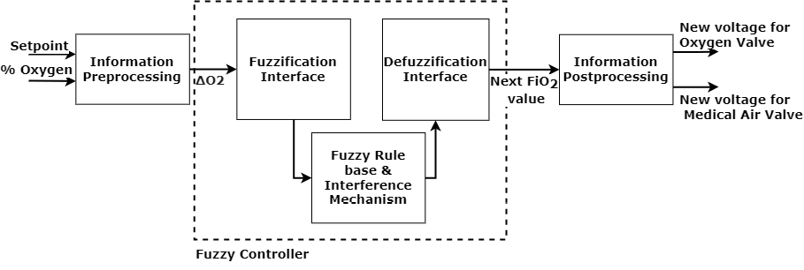
Figura 3. Fuzzy Logic controller architecture.
Control Design
The input of the control is defined by triangular signals, representing the different values according to the input value of the Fuzzification Interface block. The preprocessing of the information refers to obtaining the difference between the measurement and the adjustment point (setpoint), adjusting it to a value between -1 and 1. This according to the equation:
 (1)
(1)
On the Fuzzification Interface block, the value is taken from the equation (1). The condition 1 refers to the sign of the input value. If this is negative, the valve opens; if it is positive, the valve closes and if it is within the Zero value, the voltage value remains stable.
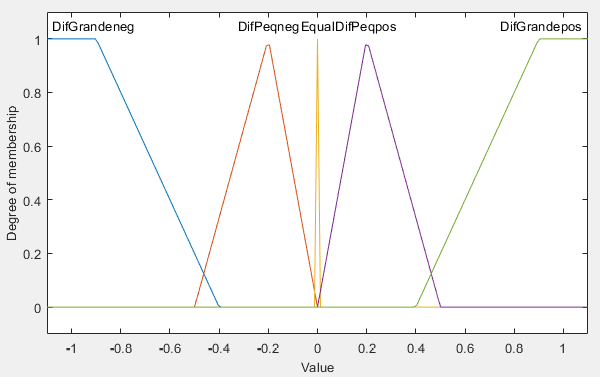
The condition 2, refers to the difference between the values that are compared in the input. You can have big differences or small differences, either positive or negative. In the event that condition 2 has a value between ±0.01, a non-significant difference is considered, so the voltage value remains stable.
These conditions are composed of triangular and trapezoidal functions as presented on figure 4, which represent the membership according to the type in each condition.
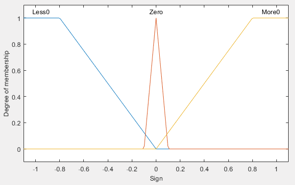
(a) Condition 1: Sign
(b) Condition 2: Value
Figura 4. Conditions for the Fuzzy Rules.
Having defined the inputs, the consequences that it can have when fulfilling the iterations between the inputs are defined. For this case, there are 5 classifications (see table III notes), each one represented by a constant depending on the case. The values of ΔO2 from 0% to ±1 must be covered to include the different changes that the control handles in its slope and to be able to generate an opening curve of the valves corresponding to said changes in ΔO2. The control has 15 different rules that allow covering the spectrum of possibilities, these are shown in the Table III.
Table 3. IF-THEN Rules used in Fuzzy Logic Controller.
|
Less than 0 |
Cond. 1 |
|||
|
Zero |
More than 0 |
|||
|
Cond. 2 |
Big Diff. Positive |
OF |
S |
CF |
|
Small Diff. Positive |
OS |
S |
CS |
|
|
Equal |
OS |
S |
CS |
|
|
Small Diff. Negative |
OS |
S |
CS |
|
|
Big Diff. Negative |
OF |
S |
CF |
|
CF: CloseFast, CS: CloseSlow, S: Steady, OS: OpenSlow, OF:OpenFast
All the rules are evaluated, and their results are added in order to obtain the fuzzy set that would be the input to the Defuzzification Interface block. This is where the value desired to adjust FiO2 appears. Then the model that allows to control the voltage provided to each valve is modeled on the Information Postprocessing block, allowing the control of the voltage provided to each valve.
The model in the Information Postprocessing block is based in the behavior of the VPPE-3-1-1/8-6-010-E1 valve, shown with the following equations:
 (2)
(2)
Where FiO2 is the desired oxygen value (coming from the control), F is the flow of the mixture (defined from the interface), VO2 is the voltage of the Valve of Oxygen and VAM is the pressure of the Medical Air Valve.
Necessary parameters for equipment validation
To properly validate this mechanical ventilator, it needs to meet criteria given by the Ministry of Health, to ensure the developed equipment has the capabilities wanted for an optimal operation in ICU.
The parameters will be briefly explained, and their wanted values are given in Table IV.
Tidal volume: Volume of air entering the lungs on a normal breath. Breathing frequency: Breathing cycles per minute.
I:E ratio: Inspiration to expiration ratio.
FiO2: Fraction of inspired oxygen, determines the percentage of oxygen in the gas supplied to the patient.
Table 4. Wanted values for the mechanical ventilator.
|
Parameter |
Wanted value |
|
Tidal volume |
Ranging from 250 to 800 mL, with 50 mL increases controlled automatically |
|
Breathing frequency |
10 to 30 breaths per minute |
|
FiO2 |
Between 21 % and 70%, variable |
|
I:E ratio |
Variable from 1:1 to 1:5 |
Safety and Effectiveness Preclinic Evaluation
As part of an animal model eight domestic pigs (Sus scrofa domesticus) were used as animal models for in vivo testing of the device. The weight ranged between 50-60 kg, and the same proportion of females and males was maintained. The sample size was calculated using the maximum estimation error of the upper limits of the risk values III and IV of the Physical Status Scale of the American Society of Anesthesiologists (ASA) (Portier and Ida, 2018) as a parameter and considering variations implicit in previous studies (Daabiss, 2011), assuming a confidence level of 95% for estimating the proportion with binary variables. The animals were kept in quarantine in the Equine and Major Species Hospital of the School of Veterinary Medicine facilities at the National University of Costa Rica, where the preclinical study was carried out. The care, handling, and preclinical procedure were carried out with the approval of the Institutional Committee for the Care and Use of Animals (CICUA for its acronym in Spanish) of this same University. Descriptive statistics for the proportions of pigs suffering device-related complications (safety evaluation) and the proportion of pigs properly ventilated (effectiveness) by the designed device after lung injury were recorded. [13, 14]
Results and analysis
The data acquisition and display subsystem for the Mix Control system are developed on the Raspberry Pi 4. The required measurements are sent via I2C protocol from the ADC and also transmit information to the PWM module for the correct adjustment of the tensions of the proportional valves. In addition, the Raspberry Pi 4 allows the processing of the graphical interface developed in Python Qt. Feedback data acquisition is obtained by the MU24903 oxygen sensor.
Figure 5 shows the response of the control in simulation when entering a set point of 100% and an initial measurement of 50% in the fraction of inspired oxygen (FiO2). In addition, an error factor of ±2% is added in the measurement to simulate the real system, defined only by the oxygen sensor. The control response in simulation has a rise time of 9.1s, a settling time of 21.42s shows no overshoot and has a steady state error of 0.0644%.
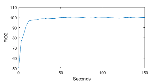
Figura 5. Response of the simulation - fuzzy logic controller.
For the results in the implementation of the control with feedback from the oxygen sensor MU24903, the conditions needed are listed as:
•The inputs of both valves must have a constant value of pressure, for the first results 50 psi was used.
•The concentration of the oxygen tank used is 95%.
•A flow of 25 l/min.
Table V shows the physical parameters of the implementation of the fuzzy logic controller in the Mix Control. It should be noted that the setpoint values were varied consecutively.
TAable 5. Results of physical parameters in the implementation.
|
Setpoint |
FiO2 (%O2) |
|
|
Actual Value |
Next value |
|
|
30 |
41,03 |
38,77 |
|
60 |
60,89 |
59,99 |
|
100 |
103,87 |
99,99 |
|
30 |
42,33 |
37,43 |
The control parameters are shown in Table VI. It has an average steady-state error of 0.2%, an overshoot of 0%, a maximum rise time of 7s, and a maximum settling time of 23s.
Table 6. Results of control parameters in the implementation.
|
Parameters |
FiO2 (%) |
|||
|
30 |
60 |
100 |
30 |
|
|
Ess (%) |
0,367 |
0,0148 |
0,0387 |
0,411 |
|
Mp (%) |
0 |
0 |
0 |
0 |
|
Tr (s) |
7 |
3 |
4 |
5 |
|
Ts (s) |
23 |
18 |
8 |
21 |
These parameters allow the Mix Control system to have a fast and robust adjustment, ensuring an accurate value of the feedback of oxygen. This guarantees that patients
with respiratory insufficiency receive the correct amount of breathing gas and the correct mixing ratio.
In order to verify the proper functioning of the designed prototype, the ventilator was put under testing using two advanced patient simulators, Gaumard HAL S3201 and Gaumard NOELLE S574.100, as preliminary tests. The tests were conducted at the Universidad de Ciencias Médicas (UCIMED) in Costa Rica on June 18th, 2020. The FiO2 was set as a variable input parameter from 21%-100%.
Apart from testing the ventilator using patient simulators, a Vernier Spirometer was used to make preliminary measures of the volume of air supplied to the lungs by the ventilator, also known as tidal volume, as well as the flow rate.
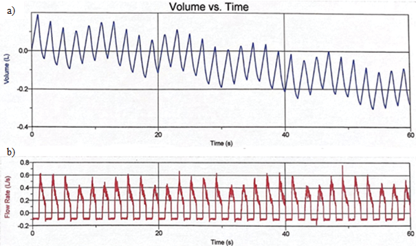
Figura 6. Lung Volume Measurements variable. a) Tidal Volume, b) Flow rate and 1:1 I:E ratio.
The figure 6a shows the variation of the tidal volume in a range of 600 mL. Figure 6b shows the results of the flow rate of oxygen in the simulator, this value starts in -0.1 L/s and reaches the maximum pike in 0.6 L/s., with a frequency of 30 breaths per minute, but with a longer time between inhalation and exhalation cycles, resulting in a 1:1 I:E ratio.
The tidal volume, breathing frequency, as well as I:E ratio observed in figure 6 are compliant with the parameters established by the Ministry of Health and detailed in the experimental section. For a preliminary test of the prototype, this is remarkably good as it means the proposed configuration is working as intended. while the design might need fine tuning to achieve the level of parameter customization required by the Ministry of Health to be fully compliant, it shows that the project is on a good track.
Regarding the evaluation of the safety and effectiveness, the device caused no complications (0% incidence for non-fatal or fatal events) to the evaluated pigs. All the cases resulted in a successfully ventilation by the device when subjects presented previous respiratory failure (lung injury).
Expanding access to life-saving respiratory assistance is largely dependent on the affordability of low-cost ventilators, especially in areas with limited resources or insufficient availability of mechanical ventilators. The goal of developing and manufacturing this affordable ventilator is to remove the financial obstacles related to conventional, more costly ones. This article explores the several elements that lead to cost reduction, including streamlined production processes, easily available material usage, and simpler design. It also looks at the trade-offs between functionality and cost-effectiveness, highlighting how crucial it is to keep the characteristics that are necessary for efficient ventilation while keeping costs as low as possible. The final price of this prototype is around 8500 USD.
Conclusions
This low-cost prototype designed to counteract an eventual shortage of ICU in Costa Rica worked remarkably well for a first prototype, giving a much needed breath to the public healthcare system in the fight against COVID-19.
The Mix Control system designed for the mechanical respirator allows the control of the oxygen concentration in the mixture through feedback with a sensor. This is tested by varying the setpoint and the results suggest the functionality of the system. This contemplates the different variations and ensures an error of less than 0.5%, which defines the gas mixing system as one with high precision. And the response of the control is optimal to the changes in the value of the oxygen because of its adaptability to minimal changes.
Preliminary tests results showed that the device could give a tidal volume ranging from 250 mL to 800 mL, a breathing rate between 11 and 30 breaths per minute, as well I:E ratios from 1:1 to 1:5. All these ranges fall in between the required values by the Ministry of Health for the ventilator to operate. It is worth mentioning that the equipment used to make the preliminary tests is used for educational purposes, so these tests only were made in order to verify the ventilator was working properly and should not be used for calibration purposes.
The next step in the development of this mechanical ventilator is to perform preclinical development alongside fine tuning of the equipment, to ensure the needed parameter customization and correct automatic operation. Once completed, the ventilator would be submitted for clinical trials.
The device under evaluation proved to be safe as it did not cause harm to the pigs; the percentage of fatal and non-fatal complications caused by the ventilator was 0% in both cases.
The device was shown to be effective in covering respiratory failure in 100% of cases with induced lung injury and ventilated with the TEC device.
References
[1] World Health Organization, “Coronavirus symptoms.” [Online]. Available: https://www.who.int/health-topics/coronavirus#tab=tab 3
[2] National Institutes of Health. (2020) Oxygenation and ventilation. [Online]. Available: https://www.covid19treatmentguidelines.nih.gov/critical-care/oxygenation-and-ventilation/
[3] American Thoracic Society, Mechanical Ventilation: Patient Education, Information Series. Am J Respir Crit Care Med, 2017, vol. 196.
[4] G. Anesi. (2019) Coronavirus disease 2019 (covid-19): Critical care and airway management issues. [Online]. Available: https://www.uptodate.com/contents/coronavirus-disease-2019-covid-19-critical-care-and-airway-management-issues/print
[5] G-TECH. (2020) Medical ventilator design details. [Online]. Available: https://www.gtech.co.uk/ventilators
[6] A. Vasan, R. Weekes, W. Connacher, J. Sieker, M. Stambaugh, P. Suresh, D. E. Lee, W. Mazzei, E. Schlaepfer, T. Vallejos, and et al., “Madvent: A low-cost ventilator for patients with covid-19,” MEDICAL DEVICES & amp; SENSORS, vol. 3, no. 4, 2020.
[7] R. R. Vicerra, E. Calilung, J. Espanola, E. Dadios, A. Culaba, E. Sybingco, A. Bandala, A. B. Madrazo, L. G. Lim, R. K. Billones, and et al., “Implementation of a programmable logic controller (plc)-based control system for a bag-valve-mask-based emergency ventilator,” 2020 IEEE 12th International Conference on Humanoid, Nanotechnology, Information Technology, Communication and Control, Environment, and Management (HNICEM), 2020.
[8] S.-Y. Lu, H. Lin, H.-T. Kuo, C.-L. Wu, W.-J. Wu, C.-H. Chen, and Y.-T. Liao, “Design and study of a portable high-frequency ventilator for clinical applications,” 2019 41st Annual International Conference of the IEEE Engineering in Medicine and Biology Society (EMBC), 2019.
[9] M. Bhujade, “Design and implementation of arduino based low cost ventilator using self inflating bag,” International Journal for Research in Applied Science and Engineering Technology, vol. 9, no. 5, p. 544–549, 2021.
[10] A. Pandey, A. Juhi, A. Pratap, A. Pratap Singh, A. Pal, and M. Shahid, “An introduction to low-cost portable ventilator design,” 2021 International Conference on Advance Computing and Innovative Technologies in Engineering (ICACITE), 2021.
[11] K. Ogata, Modern Control Engineering, 5th ed. Pearson, 2010.
[12] G. Chen and T. Pham, Introduction to fuzzy sets, fuzzy logic, and fuzzy control systems. CRC Press, 2001.
[13] Portier, K., & Ida, K. K. (2018). The ASA Physical Status Classification: What Is the Evidence for Recommending Its Use in Veterinary Anesthesia?—A Systematic Review. Frontiers in Veterinary Science, 5(AUG). https://doi.org/10.3389/FVETS.2018.00204.
[14] Daabiss, M. (2011). American Society of anaesthesiologists physical status classification. In Indian Journal of Anaesthesia (Vol. 55, Issue 2, pp. 111–115). https://doi.org/10.4103/0019-5049.79879
1 Instituto Tecnológico de Costa Rica. Costa Rica.
 aniruiz@itcr.ac.cr
 https://orcid.org/0000-0003-1300-3887
2 Instituto Tecnológico de Costa Rica. Costa Rica.
 adquesada@itcr.ac.cr
 https://orcid.org/0000-0002-5975-4195
3 Instituto Tecnológico de Costa Rica. Costa Rica.
 rchacon@itcr.ac.cr
 https://orcid.org/0000-0002-5364-4649
4 Instituto Tecnológico de Costa Rica. Costa Rica.
5 Instituto Tecnológico de Costa Rica. Costa Rica.
6 Instituto Tecnológico de Costa Rica. Costa Rica.
7 Instituto Tecnológico de Costa Rica. Costa Rica.