Analysis of a cooling system for robotic joints using a computational fluid dynamics study
Análisis de un sistema de enfriamiento para articulación robótica mediante un estudio de dinámica de fluidos computacional
María Fernanda Madriz-Ramírez1, Kevin Alberto Solano-Núñez2, Mauricio Rodríguez-Calvo3
Madriz-Ramírez, M.F.; Solano-Núñez, K.A.; Rodríguez-Calvo, M. Analysis of a cooling system for robotic joints using a computational fluid dynamics study. Tecnología en Marcha. Vol. 35, special issue. IEEE International Conference on Bioinspired Processing. December, 2022. Pág. 31-38. https://doi.org/10.18845/tm.v35i9.6488
Keywords
Heat exchanger; cooling system; humanoid robot; fluid dynamic simulation.
Abstract
The cooling system is one of the most important parts of a robot, a correct design allows it to increase its capacity while reducing the chances of a malfunction. In general, cooling systems for humanoid robots require special characteristics to not interfere with the optimal operation; aspects such as weight, size, materials, and positioning of this system are crucial for maximum efficiency. The current problem in this design is that the cooling system needs to maintain its power to perform tasks when lifting heavy weights without consequences such as reduced mobility of the joint, and therefore decrease the robot’s efficiency. In this paper, we studied, analyzed, and discarded existing options of electric motor actuators. Once the viable options were obtained, so we proceed to make a proper design, then was made a computational fluid dynamics study (CFD) to get heat extraction measurements as well as fluid velocity, essential to make the final decision, solving the initial problem.
Palabras clave
Intercambiador de calor; sistema de refrigeración; robot humanoide; termodinámica; simulación dinámica de fluidos.
Resumen
El sistema de refrigeración es una de las partes más importantes de un robot, un correcto diseño le permite aumentar su capacidad a la vez que reduce las posibilidades de un mal funcionamiento. En general, los sistemas de refrigeración para robots humanoides requieren de características especiales para no interferir en su óptimo funcionamiento; aspectos como el peso, el tamaño, los materiales y el posicionamiento de este sistema son cruciales para lograr la máxima eficiencia. El problema actual en este diseño es que el sistema de enfriamiento necesita mantener su potencia para realizar tareas al levantar pesos pesados sin consecuencias como la reducción de la movilidad de la articulación, y por lo tanto disminuir la eficiencia del robot. En este trabajo estudiamos, analizamos y descartamos las opciones existentes de actuadores de motores eléctricos. Una vez que se obtuvieron las opciones viables, por lo que se procede a hacer un diseño adecuado, luego se realizó un estudio de dinámica de fluidos computacional (CFD, por sus siglas en inglés) para obtener las medidas de extracción de calor y la velocidad del fluido, esenciales para tomar la decisión final, resolviendo el problema inicial.
Introduction
Currently, at the Universidad Técnica Nacional, the program (Design of a proprioceptive robotic arm for robotic limbs with practical applications in humanoid robots) is under development in the degree course in Electronic Engineering, which consists of the creation of a robotic arm with qualities of handling heavy objects in everyday life, however, it has encountered some difficulty regarding an optimal solution for its cooling system. Therefore, the contribution of engineering in industrial production in this research focuses on the need to investigate, study, and analyze improvements about liquid cooling systems in motors for robotic joints, which adapt to the specifications of the joint of the humanoid robot.
For the optimal operating of any robot, a set of various important factors are required, one of the most important is the cooling system. The main objective of the cooling system is to prevent the joints from overheating, especially when working under high-demand tasks. When an adequate temperature is maintained, higher efficiency is obtained, and therefore a lower exposure to a possible failure is achieved [9]. To enable robots as effective assistants they need a certain power to perform tasks that require lifting a lot of weight generating a high energy demand, current solutions have been based on adding very large mechanical reductions, this is not a viable solution, since it adds more weight and decreases mobility [14][15].
Humanoid robots pretend to simulate a human body and its functions, many of them use electric motors to generate this joints movement, some problems related to robots, especially when we talk about dynamic ones, are the overheating of their joints, which is why, at the University of Tokyo, Japan, they built a humanoid robot called KENGORO, which has a mechanism that simulates sweating to control the temperature of its electric motors [1]
[11][13].
The humanoid Kengoro robot is powered by 108 motors, but what is truly amazing about this robot is that it can sweat, thanks to its innovative cooling system. Like all human beings, robots generate heat when they perform their tasks, so the mechanism used by the robot to simulate artificial perspiration is in question a cup of deionized water, a type of purified water that lacks salts and minerals. dissolved. Water bubbles through the porous framework and is replaced every 12 hours or so. What they do is take advantage of the metal structure of the robot, which normally uses it for support but this time it is used to fill the metal structure with water and kept it cold, so the clever layers of the perforated structures allow the water would run through channels inside the skeleton, pass to an outer level and evaporate, all without a wet robot dripping onto the floor [9].
Stanford scientists and researchers at Stanford University are also exploring new methods to keep robots cool with tiny holes, they showed a new type of breathable plastic fabric with nanometer-sized pores that could absorb body radiation [8][12].
In short, a cooling system is a mechanism based on the principles of thermodynamics and fluid mechanics, they are designed to transfer thermal energy between two sources. These are also designed as a thermodynamically closed system, they prevent the motor from overheating; first, the liquid allows to absorb the heat generated in the motor, then this heat is transferred into the air. These are some of the reasons why water is normally used because first, it has a great heat transfer coefficient without increasing the system temperature, in addition, it has a lower pollution impact, on top of that’s it is inexpensive [3].
Methodology
The following section will show the 3D design of the heat exchanger, a vital part of the cooling system, variables of weight, mass, and volume are considered, in addition to the other parts that are assembled such as the robotics joints, copper pipes, cables, the pump, and mechanical support. In this part, the design methodology that is applied, efficiency is conformed of six steps [2].
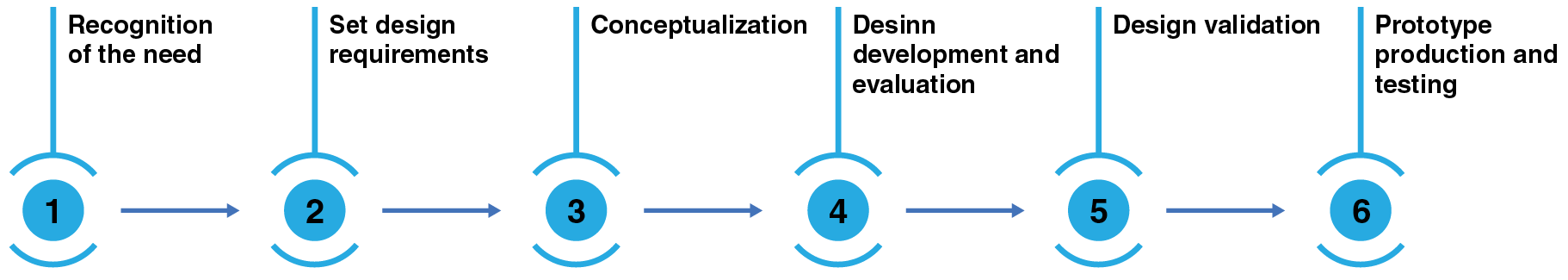
Figure 1. Methodology
As it was mentioned before, the central part of a cooling system is the heat exchanger, which acts as a regulator of temperature on the liquid used, additionally the pump is the center of the cooling system, it moves the liquid through all the internal conductors, as if it were an inner cardiovascular system. For this part, the calculations to determine the dimensions of the radiator and its design was made with CAD software, all the process is shown hereunder. To obtain the heat exchanger dimension was necessary to calculate the calorific power, which is represented with  , this data shows how much heat must be dissipated by the cooling system. Using the Pmax = 880.88 W, the engine maximum´s power and the motor efficiency have a value of 0.91. The nomenclature used on these formulas will be shown above [2].
 (1)
(1)
The heat obtained to dissipate from the system was 79.27 W, now we proceed to calculate the calorific power of de refrigerant ( ), using and a value of 1.1 that was applied as a safety factor to prevent the continuous fouling of the radiator [2].
 (2)
(2)
Now to calculate the radiator area (Arad) using the = 87.21 W, the value of the heat transfer coefficient of the oil (h) = W/m2 K and the oil inlet temperature (Tin.oil) and the air temperature Tair being 313.15 K and 293.15 K, respectively. And The value obtained of Arad is 2.18 m2
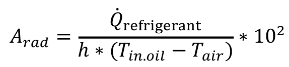 (3)
(3)
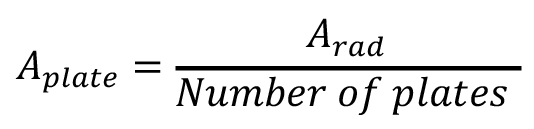
Next the radiator area (Arad) was divided into 35 plates to reduce the size of the heat exchanger, the area of each plate is 0.062 m2.
 (4)
(4)
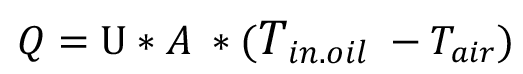
Now to be able to verify this the following formula is applied, where U represents the aluminum heat transfer coefficient, A is equal to the plate area and must show a result value close to the output power of the motor, which is the dissipated heat, Tin.oil is the temperature entering the radiator, and Tair is for the ambiental temperature.
 (5)
(5)
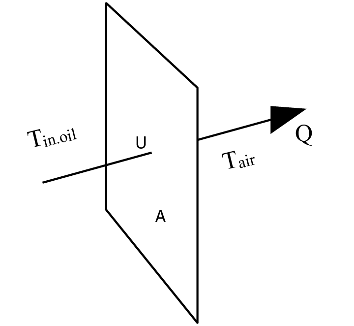
Figure 2. Calculate the heat (Q) to dissipate
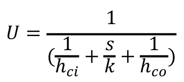
Next, the heat transfer coefficient of aluminum was calculated with the following formula:
 (6)
(6)
Where, U is the total heat transfer coefficient (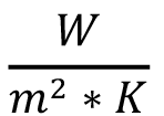 ), k is thermal conductivity of the material (
 ), hci and hco are the individual fluid convection heat transfer coefficient of the interior or exterior wall (
 ) and s is the plate thickness (m) [5][6]. The value obtained of U is 54,58 W/m2 K, then proceed to calculate the heat to dissipate, a single plate was used, this was represented with a Q, the result was Q = 2368.77 W. Next step was to obtain the same heat to dissipate with the difference that this time 35 plates was used, represented with the same Q, the result was Q = 2368.77 W. Finally, with a 2.18 m2 heat exchanger, it is possible to dissipate the necessary heat established by the formulas. In this analysis the use of a fan is not considered, to have a more compact and lighter design.
The heat exchanger was designed with SolidWorks, this software allows modeling, simulation, and management of 3D solids. In addition, through simulations is possible to observe the way the models would work in real circumstances. Meanwhile to obtain the simulation first was necessary to sketch the plates and tubes using a 2D simulation, then using different commands the modeling of the solid took the shape needed, at the same time the design of the radiator was based on a type of heat exchanger with smaller area and volume called compact. The plates have a square shape of length of 249 mm and width of 249 mm, with an area of 62001 mm2, which is the area of the plates according to formula number 4. When multiplied by 35 (number of plates) an area of 2170035 mm2 was obtained which is also the area of the radiator according to formula number 3. In addition, each plate has 30 holes of 9.55 mm diameter, distributed in three columns of five holes each, with a distance between them of 48 mm, between 98.5 mm columns, 5 mm thick, and with a total mass of 3,084 kg. Thus, the tubes have an internal diameter of 8 mm and an external diameter of 9.55 mm, a length of 340 mm, a height of 192 mm, and a total mass of 4,593 kg. Finally, by joining all the pieces through the assembly function, a radiator with the following dimensions was obtained, with a mass of 7.68 kilograms, and a surface area of 4.86m2, all conformed with aluminum plates and copper tubes.
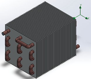
Figure 3. The final design of the heat exchanger.
Results
For the first CFD simulation, the system was analyzed based on the following conditions: environmental conditions a temperature of 20.05 °C and a static pressure of 101.325 Pa, for solid conditions they have an initial temperature of 19.00 °C and the liquid used in the simulation is olive oil that shares properties with dielectric oil. Now for the input conditions, there was a temperature of 45 °C, an ambient pressure of a temperature of 20.05 °C and static pressure of 101.325 KPa and a heat transfer coefficient of 55.45  for the outer wall. The following results were obtained: The liquid temperature decreases when passes through the radiator, it enters at around 50 °C and gets out approximately at 30 °C, a difference of 20 °C.
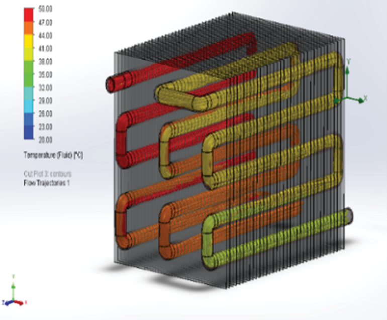
Figure 4. Flow trajectory and temperature.
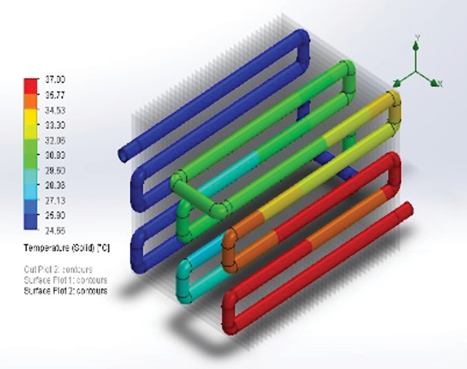
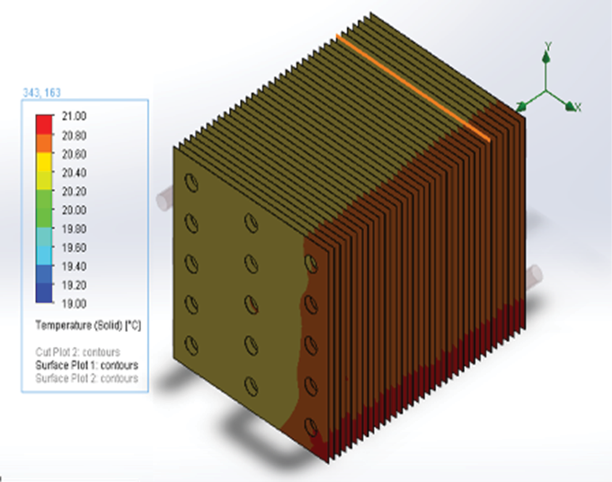
Finally, the temperature of the plates and tubes at the end of the simulation had an average temperature of 21 °C and 37 °C respectively when they were initially 19 °C and 17 °C, showing an increase of temperature of 2 °C and 22 °C respectively.
|
|
|
|
Figure 5. Plates temperature |
Figure 6. Tubes temperature |
In various experimental studies of refrigeration systems, the difference temperature when measuring the inlet and outlet temperatures is in one of the studies approximately 15 °C to 18 °C, in another a little lower than 6 °C to 10 °C [4][7]. Therefore, in this analysis, when performing the simulation in the computer, it generates a result that, according to the design of the heat exchanger, can reduce the refrigerant temperature by approximately 20 °C, being a little higher than what can be seen in the studies mentioned, but it can be expected that it will be lower when doing the experimental test with the radiator or exchanger already built, even so, the objective of dissipating a good amount of heat while keeping the engine cooled is achieved.
Conclusions
In conclusion, thanks to the 3D design and its results it was possible to find the dimensions of the heat exchanger that can supply the necessities of the cooling system; therefore, it will be able to adapt the prototype that best illustrates the needs of the robotic joint. Additionally, using CFD simulation was the key to proving that the designed prototype of the heat exchanger can extract the heat efficiently since the first simulation does achieve the objective of extracting a significant amount of heat, reducing the temperature of the oil from 50 °C to almost 30 °C.
References
[1] Ackerman, E. (2016). This Robot Can Do More Push-Ups Because It Sweats. Recuperated of https://spectrum.ieee.org/automaton/robotics/humanoids/this-robot-can-do-more-pushups-because-it-sweats.
[2] Cabrera, Franklin. Tigre, E. (2016). Diseño y construcción de los sistemas de refrigeración de un vehículo formula SEA eléctrico [Tesis de Ingeniero Mecánico Automotriz, Universidad Politécnica Salesiana]. Repositorio institucional - Universidad Politécnica Salesiana.
[3] Cegel, Y. Boles, M. (2014). Termodinámica. México. Octava Edición. McGraw Hill.
[4] Martin, H. (2019). Diseño del sistema de refrigeración de un vehículo de fórmula SAE. [Tesis de Ingeniería Mecánica, Universidad Carlos III de Madrid]. Repositorio institucional - Universidad Carlos III de Madrid.
[5] Engineers Edge. (2021). Convective heat transfer coefficients. Recuperated of https://www.engineersedge.com/heat_transfer/convective_heat_transfer_coefficients__133.
[6] Engineering ToolBox. (2003). Overall Heat Transfer Coefficient. [online] Recuperated of https://www.engineeringtoolbox.com/overall-heat-transfer-coefficient-d_434.html.
[7] Gavilema, H. (2014). Estudio teórico y experimental de los parámetros de funcionamiento de un motor de combustión interna a gasolina a diferente concentración de agua-refrigerante [Tesis de Ingeniero Mecánico Automotriz, Escuela Superior Politécnica de Chimborazo]. Repositorio institucional - Escuela Superior Politécnica de Chimborazo.
[8] Guarino, B. (2016). The amazing sweating robot. EU: The Washington Post. Recuperated of https://www.washingtonpost.com/news/morning-mix/wp/2016/10/17/the-remarkable-sweating-robot-researchers-cool-overheating-machines-in-human-style/
[9] Hernández, R., Fernández, C., Baptista, P. (2010). Metodología de la investigación. McGRAW-HILL. (Original publicado en 1991).
[10] Jaramillo, O. (2007). Intercambiadores de calor. Centro de Investigación en Energía. Universidad Nacional Autónoma de México. http://www.cie.unam.mx/~ojs/pub/HeatExchanger/Intercambiadores.pdf.
[11] Kakiuchi, Y. ET. AL. (2015). Development of humanoid robot system for disaster response through team NEDO-JSK’S approach to DARPA. Corea del Sur: IEEE.
[12] Kubota, T. (2017). Stanford researchers develop a new type of soft, growing robot. Stanford, EU: Stanford News. Recuperated of https://news.stanford.edu/2017/07/19/stanford-researchers-develop-new-type-soft-growing-robot/
[13] Pia, M. ET. AL (2016). Direct Liquid Cooling in Low-Power Electrical Machines: Proof-of-Concept. Japan: IEEE.
[14] Rodríguez, M. Ruiz, F. (2019). Comparative efficiency study of two proposed designs tested in water- and air-cooling conditions for a high-power humanoid robot hollo joint. Costa Rica. INII.
[15] Rodríguez, M. Ruiz, F. (2019). Torque sensor geometry study on 3D simulated conditions for a Hollow robotic joint. Costa Rica. INII.
1 Universidad Técnica Nacional. Costa Rica. E-Mail: mamadriz@est.utn.ac.cr https://orcid.org/0000-0001-9922-9398
2 Universidad Técnica Nacional. Costa Rica. E-Mail: knsolano@est.utn.ac.cr https://orcid.org/0000-0002-2805-1091
3 Universidad Técnica Nacional. Costa Rica. E-Mail: mrodriguezc@utn.ac.cr https://orcid.org/0000-0002-3737-2866