A novel diagnosis system concept for Safe Distributed Systems
Un novedoso concepto de sistema de diagnóstico para Sistemas Distribuidos Seguros
Javier Dario Leon-García1, Sebastian Imle2
Leon-García, J.D; Imle, S. A novel diagnosis system concept for safe distributed systems. Tecnología en Marcha. Vol. 34, especial. Movilidad Estudiantil. Octubre 2021. Pág 19-27. https://doi.org/10.18845/tm.v34i5.5910
Keywords
Diagnosis system; distributed system; safety; system architecture; state machine.
Abstract
This article is based on the design of a diagnosis system for the Energize to Trip Actuation System (ETTAS). The ETTAS project proposes a sustainable and safe alternative to operate valves in subsea production systems without contaminating the subsea with hydraulic fluids. As this is a Safe Distributed System, its design requirements seek a Safety Integrity Level of 2 (SIL 2), which involves an implementation of a diagnosis system. The diagnosis system presented here is a concept which can be applied to Safe Distributed Systems in general. The method used to design the Diagnosis System Concept involves the formulation of requirements, the generation of a knowledge base, the approach and selection of proposals, and the design of the final concept. The resulting concept is shown by means of state machines and a Diagnosis System Architecture. It is concluded that the concept increases the diagnostic capabilities in the Safe Distributed System since it is time independent to change states, it minimizes the amount of functionalities and takes advantage of shared memory to make it feasible to diagnose different components in the system.
Palabras clave
Sistema de diagnóstico; sistema distribuido; seguridad; arquitectura de sistema; máquina de estado.
Resumen
El presente artículo está basado en el diseño de un sistema de diagnóstico para el Energize to Trip Actuation System (ETTAS). El proyecto ETTAS propone una alternativa sostenible y segura para accionar válvulas en sistemas de producción submarina sin derramar fluidos hidráulicos contaminantes en el fondo marino. Al ser este un Sistema Distribuido Seguro, sus requerimientos de diseño buscan un Safe Integrity Level 2 (SIL 2), lo cual hizo necesaria la implementación de un sistema de diagnóstico. Éste último es presentado aquí como un concepto para ser aplicado en Sistemas Distribuidos Seguros en general. El método utilizado para el diseño del Concepto del Sistema de Diagnóstico involucra el planteo de requerimientos, la generación de una base de conocimiento, el planteamiento y selección de propuestas y el diseño del concepto final. El concepto resultante es mostrado a través de máquinas de estado y una Arquitectura del Sistema de Diagnóstico. Se concluye que el concepto incrementa las capacidades de diagnóstico en el Sistema Distribuido Seguro ya que es independiente del tiempo para cambiar sus estados, minimiza la cantidad de funcionalidades y se aprovecha de la memoria paralelamente compartida para ser implementable para diagnosticar distintos componentes en el sistema.
Introduction
Distributed systems encompass many of the most significant technologies of recent years. They comprise a wide range of systems, but for the purposes of this document, it is focused in localized distributed systems which can be found in Aircrafts, Vehicles, or in Subsea Production Systems for example. All of them contain several independent hardware and/or software elements, usually known as nodes [1]. They communicate and coordinate actions by exchanging messages [2], as a collection of systems that intercommunicate themselves to achieve a complex function.
Adding the safety property to the previous definition, involves certain specifications in it. The most relevant, regarding this document, are a safe communication and a Diagnostic Coverage. These additions can be evidenced by Nagaura [3] for example, where the invention of a highly reliable distributed system made up of fifteen systems performs a safe communication by ensuring that message data is not corrupted during the process of sending and receiving of a message. Secondly, the Diagnosis Coverage (DC) is the ratio of the detected failure rate to the total failure rate of the system [4]. The DC has an indirect influence in a requirement of safe distributed system known as Safe Integrity Level (SIL).
The SIL is a discrete level for specifying the safety integrity requirements of the safety functions to be allocated to Electrical/Electronic/Programmable Electronic safety - related systems [5].There are four different levels where the safety of a system can be categorized, where SIL 4 is the highest level of Safety integrity [6]. To get a high SIL, one of the strategies that the design of a system can include is to reach a high DC through a high detectability of dangerous failures by a diagnosis system, as it is shown by Leon [4]. To diagnose a failure is critical in the DC, but also the spurious effect is highly relevant for the safety in systems. That is why diagnosing a system is especially difficult, because they must be validated to guarantee their integrity in the DC to have effect in the SIL.
The design of the diagnosis system mentioned before is the main topic of the present document. A diagnosis system is defined as a type of supporting system that gives possible explanations about the failures in a target system through the collection and analysis of information about the system status [7] [8]. According to Leon [4], diagnosis systems are an integral part of machines and devices having complex technological functions, such as components in distributed systems. Moreover, it is known that diagnostic capability of a system has a high impact on the design of safe distributed systems [9], since the increase of components and functionalities comes with a higher potential for failures.
Nowadays, the implementation of diagnosis systems in distributed systems has taken more importance due to the continuously increasing demand in higher system standards from the society as well as the increasing complexity of overall system design in general. For example, Kulkarni [10] has proposed an innovative technique to detect faulty nodes in a distributed system by using an accurate estimation model to find out which node would be more likely to be faulty; Kandasamy [11] presents us with a method to diagnose actuators in distributed fashion using processors, in order to provide a global view of their faulty status and shut them down before the system reaches an unsafe or a critical condition.
In accordance with the examples above, the diagnosis concept presented in this document was designed for the ETTAS project of Aalen University. This consists of a system architecture and operational strategies for high safety and reliable motion control systems [4]. The design is intended to perform an energize-to-trip safety function whenever it is required to by a subsea production system [4]. The energize-to-trip function is a novel subsea actuation concept proposed by ETTAS because, unlike current hydraulic subsea safety valves, it implements a mechatronic actuation system to close valves without contaminating the subsea with hydraulic fluids [12].
To guarantee that the ETTAS system would be able to safely perform such an important function, it has the goal to reach an SIL 2 [4]. As said before, this implies that diagnosis systems must be implemented to keep track of the operational capability of the system. As safety plays a big role in the above-mentioned subsea system, it is known throughout the document as Safe Distributed System.
For a better understanding, an explanation of terms used in this document are explained as following. The Target Component is the component that belongs to a node that is intended to be diagnosed. Diagnosis Test is one of multiple tests that the diagnosis system can perform in the Target Component to obtain specific desired information. The Diagnosis System Architecture is basically diagrams of software and hardware elements that shows the relation among them, while a Diagnosis System Concept is referred as the step design of concept in a normal design procedure, which in this case encompasses the Diagnosis System Architecture and other elements.
Method
Figure 1 summarizes the method used to reach the design the Diagnosis System Concept.
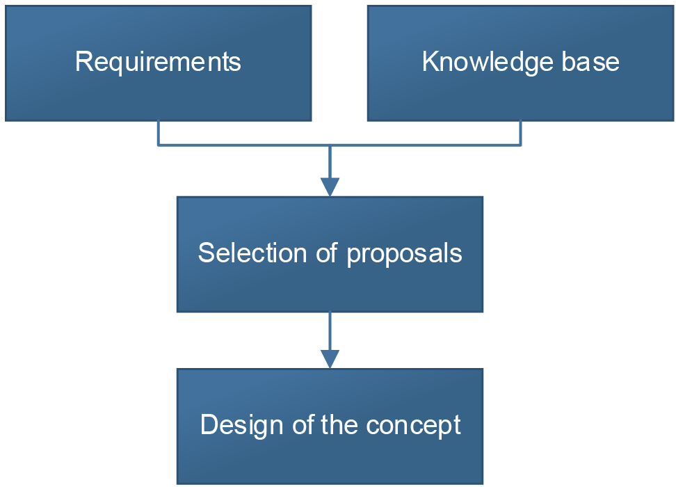
Figure 1. Method used to design the Diagnosis System Concept.
It starts with the requirements and knowledge base. These two steps are done parallel to each other because the requirements are normally written while the knowledge base is being built. The knowledge base is an essential first step of diagnosis systems. In fact, Krysander [7] asserts that “diagnosing a system is a delicate task that requires a good knowledge of the system”. Moreover, as distributed systems have a high level of complexity, it is totally needed to have a high knowledge of the system as well to make proposals in the design that can improve the reliability. By last, techniques to analyze diagnosis systems like FMEDA (Failure Mode and Effects Analysis), recognized by standards like IEC 61508 (International Electrotechnical Commission), considers the generation of a knowledge base about the system [4].
Leon [4], developed the knowledge base with three different studies. First, the hierarchy structure of the Safe Distributed System is decomposed and represented in terms of failure modes. Secondly, all the measurements in the system are listed to be further related to the studied failure modes. Finally, the Target Component is decomposed into the simplest level of the hierarchy structure in order to relate failure modes to it and identify where and how could it potentially fail.
The selection of proposals considers two steps. First, the proposals are made regarding the nature of the diagnosis system in concern. This considers the detection of boundaries where the Target Component can move. Moreover, proposals of the behavior of the Target Component during a Diagnosis Test are made in this step. By last, proposals of the failures that can occur in the system come from knowledge base. These proposals are then evaluated through a desired evaluation method. The optimal proposals are hence selected based on the evaluation criteria and the requirements.
The selected proposals plus the fulfillment of the requirements formulates and gives shape to the method used for the design of the Diagnosis System Concept. The algorithm involved can be represented through state machines, flowcharts, UML charts, tables, or any other kind of representation that shows the functioning principles of the concept.
Results
The resulting Diagnosis System Concept is presented by means of the diagrams shown in this section. This stage was achieved after the procedure explained in the method section.
Figure 2 shows an overview of the state machine to implement a Diagnosis Test as software. A single state machine is implemented in the Safe Distributed System controller, which means that it is in a different node than the Target Component. Additionally, two states are added to the Target Component to execute commands from the diagnosis system.
It is worth mentioning that each state in figure 2 can be composed of a substate machine. This makes the debugging of the diagnosis system easier to carry out since the sub state where the failure could occur can be saved as part of the diagnosis results. Consequently, the failure detection capability is greatly improved.
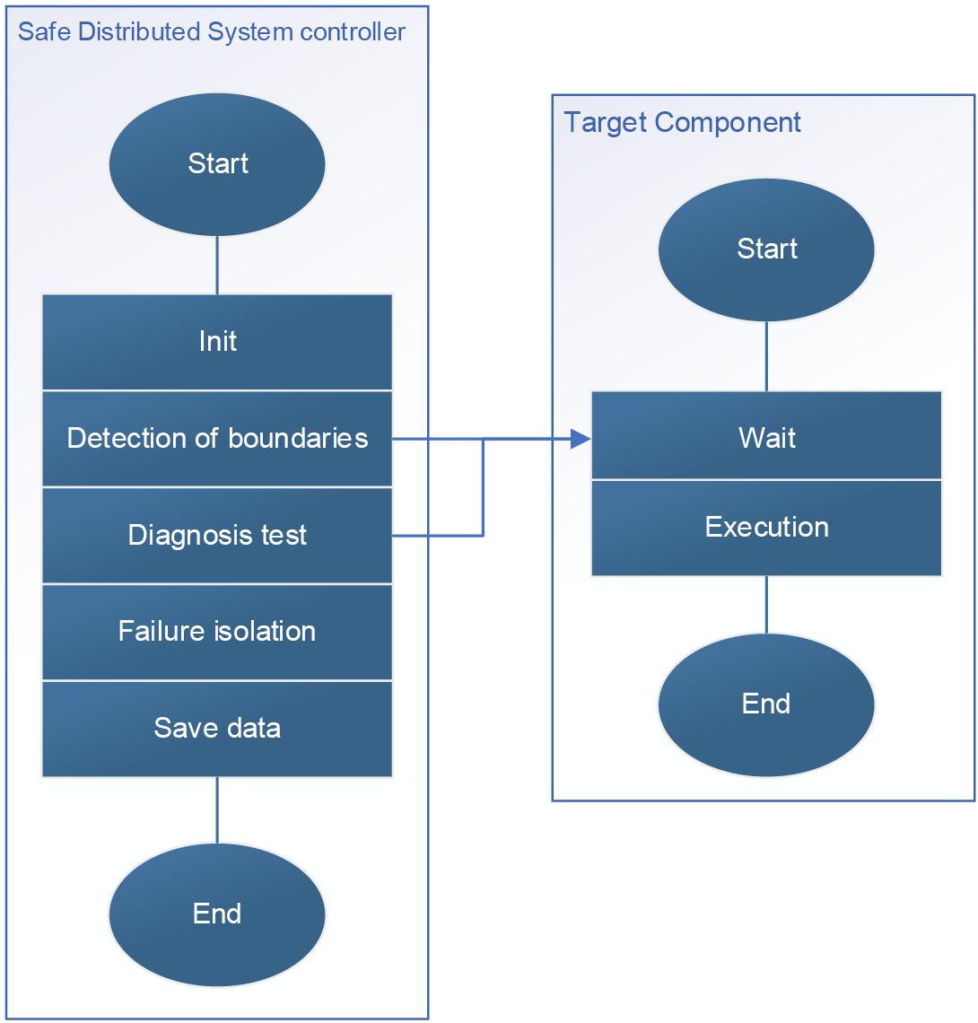
Figure 2. State machine of the software of a Diagnosis Test [4].
Figure 3 shows the state machine in the Target Component that needs to be diagnosed, in other words, it is a zoomed view of the state machine in the Target Component shown in figure 3. The state machine has three operating modes namely normal operation (NOP), diagnosis (DIAG) and safety failure request (SFR). Generally, components have a NOP mode when they consistently perform their intended function in the system. In Safe Distributed Systems, components could have an operation mode for SFR, which has priority over other states and its existence fulfills the safety requirements of the system. The DIAG state allows the component to perform needed functions and execute commands while running Diagnosis Tests in the system. Nevertheless, the DIAG state has lower priority in the state machine.
It is worth mentioning that these three operation modes are divided into two different states: WAIT and EXE. In the WAIT state, the component waits for the commands from a controller while the system is in the corresponding operation, while in the EXE state, it executes commands that come from the controller.

Figure 3. State machine in the Target Component [4].
Figure 4 shows a block diagram of the top view of the Diagnosis System Architecture. This diagram is a generalization of the architecture shown in [4]. There are two levels of blocks based on hardware hierarchy. The first level consists of implemented hardware and the second level involves functionalities programmed in the hardware. As a result, the first level consists of the Safety Software, Safe Communication Channels, the Diagnosis Embedded Processor, the Diagnosis Memory Data, and the Device Memory Data. The second level consists of the Diagnosis Manager and Diagnosis Tests. Moreover, the blocks are connected by arrows known as transitions.
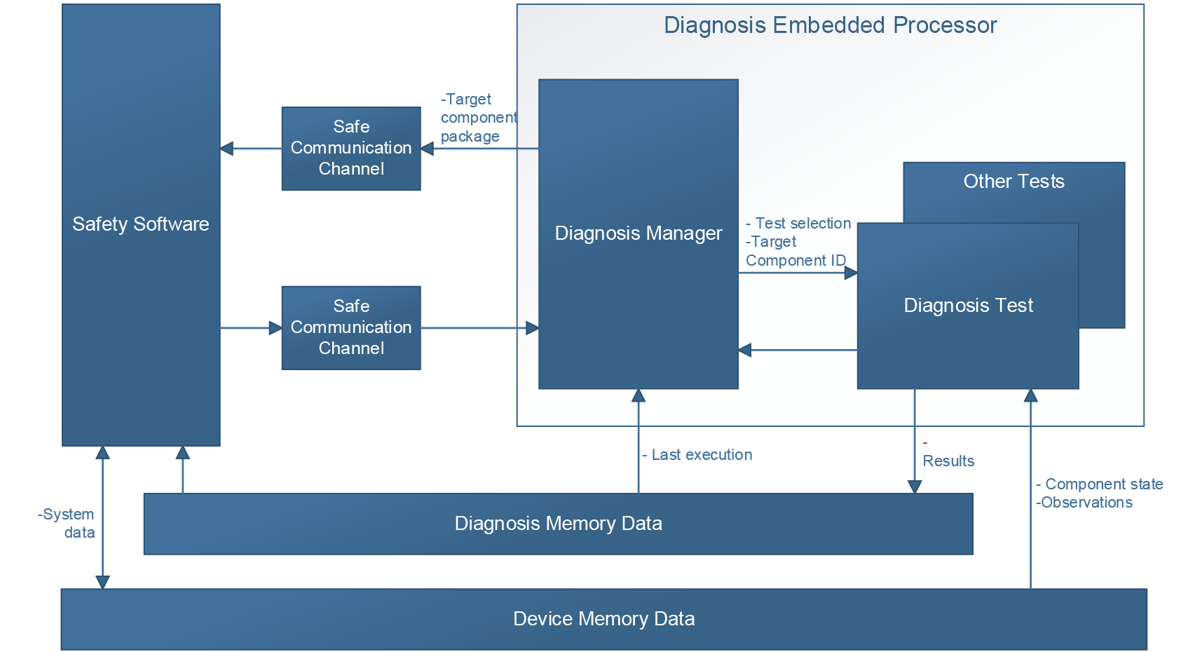
Figure 4. Top view of the diagnosis system architecture.
First level
The Safety Software is one node of the Safe Distributed System. Every command to the Target Component goes first to the Safety Software to perform a safe communication via Black Channel [4] [9]. The Diagnosis Embedded Processor is another node in charge of managing the diagnosis system. The Safe Communication Channels represent the communication interface between the Safety Software and other nodes. The Diagnosis Memory Data contains results of the Diagnosis Tests carried out by the Diagnosis Embedded Processor. The Device Memory Data stores the actual status data of the Safe Distributed System. The physically separated memories are owned by a single processor. The owner has the right to read and write this memory, the other nodes have read-only access rights if necessary. A separate safety concept based on interlocked dual-ported internal block RAM (BRAM) of the controller is developed for the access without interference.
Second level
According to Leon [4], the Diagnosis Manager manage and execute all the Diagnosis Tests. The Diagnosis Test is performed to get information about the Target Component, however other Diagnosis Tests can be carried out in different nodes to generate more diagnosis information about the entire Safe Distributed System.
Transitions
The transitions in figure 4 can be read as a point of view of the Diagnosis Test with the following logic in order to get an easy understanding of their functionality:
•The Diagnosis Test takes the ID of the Target Component and its execution command from the Diagnosis Manager as input.
•During the execution, the Diagnosis Test can read the Target Component information by accessing the Device Memory Data.
•To send commands to the Target Component, the Diagnosis Test builds a package and sends it through the Safe Communication Channel. The Safety Software receives the package and executes the command in the Target Component, after which it actualizes the Target Component information in the Device Memory Data.
•The results of the Diagnosis Test are written in the Diagnosis Memory Data so that the Diagnosis Manager can access them.
•The Diagnosis Manager uses the result named “last execution” from the Diagnosis Memory Data to schedule a new execution of the corresponding Diagnosis Test.
Conclusions
The main advantage of the presented Diagnosis System Concept is that it is not time dependent but is instead dependent on the change of states. This means that the diagnosis system is not influenced by timeout failures, so the time when diagnosis commands are executed is not relevant for it. The only way to change states in Figure 2 is by the compliment of statements plus the correct state changing in Figure 3. The timeout detection is implemented in the safe communication software. Nevertheless, the time which the Target Component requires to update its information in the Device Memory Data shall not be critical to the bus timing. Therefore, requirements like a long baud rate of communication between nodes due to safe communication does not constraint the Diagnosis System Concept. In fact, Birman [13] asserts that many distributed systems detect failures using timeouts, which is a problem since it forces the application to overcome inaccurate failure detections in software.
The Diagnosis System Concept considers a synchronization of states between the Safe Distributed System controller and the Target Component. As Safe Distributed Systems are complex systems, the synchronization between nodes makes the designed diagnosis system generic enough to be applied to a wide variety of distributed systems.
The designed concept keeps the integrity of the Target Component since it does not implement additional functions on it. The only requirement of this concept is that the Target Component has two states to execute diagnosis commands. These diagnosis commands can come from different Diagnosis Tests, which are carried out by the Diagnosis Embedded Processor.
Finally yet importantly, the fact that the concept takes advantage of the parallelly shared memory characteristics of this Safe Distributed System. This is a family of systems where multiple processors share memory, in this case the Device Memory Data. This property, the time independency, and the reduction of new functions in the Target Component increases the diagnostic capabilities of the Safe Distributed System. This basically means that the concept is able to be implemented for different nodes in the Safe Distributed System.
Recommendations
This diagnosis concept was developed for a specific Diagnosis Test of the ETTAS project. Therefore, it is recommended to use the concept to diagnose other components in the nodes of the mentioned Safe Distributed System. This could lead to a more generalized Diagnosis System Concept, which would be able to increase its diagnostic capabilities. After implementing said concept in a desired component, an analysis like the FMEDA can be performed to get the respective SIL of Target Components and evaluate the impact of the Diagnosis System Concept in the Safe Distributed System.
The state machine in the Safe Distributed System controller depends on the safe communication software to send commands and reads data from the components. To achieve a safe communication low baud rates of communication could be required in the safe communication software. Consequently, the concept designed can find limitations to diagnose variables of the Target Component that require a sampling rate greater than the baud rate of communication.
References
[1] M. van Steen and A. S. Tanenbaum, “A brief introduction to distributed systems”, Computing, vol. 98, no. 10, pp. 967–1009, 2016. [Online]. Available: https://link.springer.com/article/10.1007/s00607-016-0508-7.
[2] G. F. Coulouris, J. Dollimore, and T. Kindberg, “Distributed systems: concepts and design”. pearson education, 2005. [Online]. Available: https://ce.guilan.ac.ir/images/other/soft/distribdystems.pdf
[3] W. Nagaura, T. Yokoyama, S. Suzuki, S. Kuragaki, and T. Imai, “Highly reliable distributed system”, US Patent 6,779,138, Aug. 2004. [Online]. Available: https://patents.google.com/patent/US6779138B2/en.
[4] D. Leon, “Design of the sweep test diagnosis system for an actuating mechatronics system in safe subsea applications”, 2020.
[5] Exida, “IEC 61508 Overview Report: A summary of IEC 62508 Standard for functional safety of Electrical/Electronic/Programmable Electronic Safety-reliable systems”, 2006, [Online] Available: https://www.win.tue.nl/~mvdbrand/courses/sse/1213/iec61508_overview.pdf
[6] M. Catelani, L. Ciani, V. Luongo, and R. Singuaroli, “Evaluation of the safe failure fraction for an electromechanical complex system: Remarks about the standard iec61508”, in 2010 IEEE Instrumentation & Measurement Technology Conference Proceedings, IEEE, 2010, pp. 949-953. [Online]. Available: https://ieeexplore.ieee.org/abstract/document/5488034.
[7] M. Krysander, “Design and Analysis of Diagnostic Systems Utilizing Structural Methods”, 1038. 2003, isbn: 917373733X. [Online]. Available: http://citeseerx.ist.psu.edu/viewdoc/download?doi=10.1.1.140.9150&rep=rep1&type=pdf.
[8] M. Amarowicz, “Designing of the Diagnostic Systems Based on the Sets of Requirements”, Machine Dynamics Research, vol. 39, no. 1, pp. 125-134, 2015, issn: 2080-9948. [Online]. Available: https://yadda.icm.edu.pl/yadda/element/bwmeta1.element.baztech-07b2e969-92a7-47ed-8d03-3d03c9b9dec2
[9] S. Imle, T. Winter, J. Popp, M. Glaser, B. Bertsche 2019. Safety and reliability analysis of an actuation system, European Safety and Reliability Conference 2019, Hannover. DOI: 10.3850/978-981-11-2724-3-0885-cd
[10] P. Kulkarni, V. Deshpande, L. Sarna, S. Shenolikar, and S. Kelkar, “Fault diagnosis for distributed systems using accuracy technique”, arXiv preprint arXiv:1812.07771, 2018. [Online]. Available: https://arxiv.org/ftp/arxiv/papers/1812/1812.07771.pdf.
[11] N. Kandasamy, J. P. Hayes, and B. T. Murray, “Time-constrained failure diagnosis in distributed embedded systems: Application to actuator diagnosis”, IEEE Transactions on parallel and distributed systems, vol. 16, no. 3, pp. 258–270, 2005.[Online]. Available: https://ieeexplore.ieee.org/document/1388215.
[12] S. Imle, “Architectural Design of an Embedded Safety Controller”, 2018.
[13] K. Birman, “Reliable distributed systems: technologies, web services, and applications”. Springer Science & Business Media, 2005. [Online]. Available: https://cryptorating.eu/whitepapers/TON/References/2005-Book-Reliable%20Distributed%20Systems.pdf
1 Mechatronics Engineering Academic Area, Costa Rica Institute of Technology. Cartago, Costa Rica. Email: darox72leon@hotmail.com https://orcid.org/0000-0002-0520-9386
2 nstitute of Machine Components, University of Stuttgart. Stuttgart, Germany. Email: sebastian.imle@gmx.de